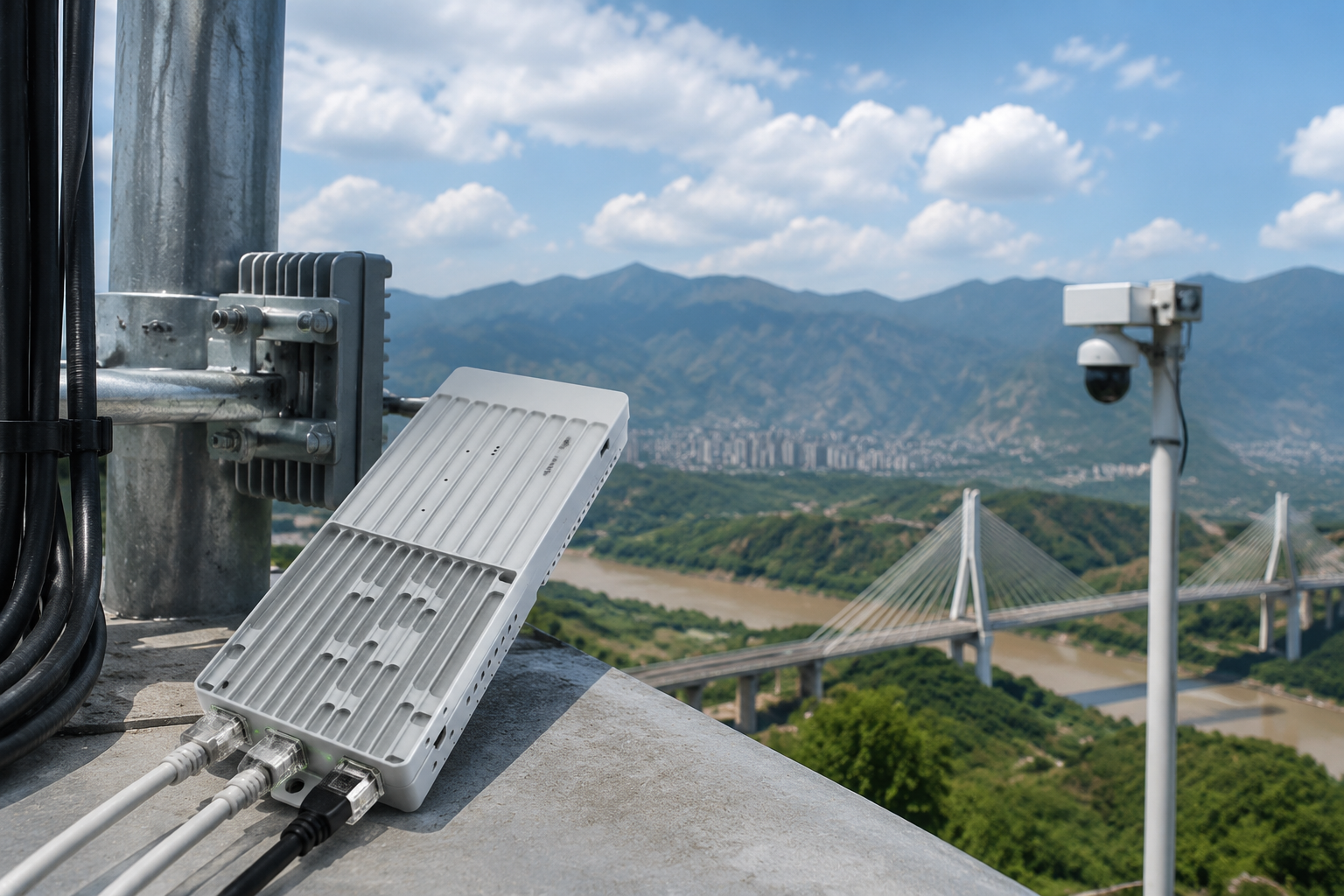
A wireless bridge for remote video surveillance connects cameras at a remote site to a recorder, monitoring station, or network without running copper or fiber between locations. A reliable design starts with the traffic requirements and physical path—not with a claimed maximum distance.
For most deployments, first map every camera and control device, calculate peak bandwidth, confirm line of sight and Fresnel clearance, then select a point-to-point or point-to-multipoint architecture. Verify Ethernet, serial, power, mounting, environmental, and management requirements before installation. A link that works in a basic test may still fail under full video load, rain, interference, or changing network conditions.
Map Cameras and Traffic Before Choosing Hardware
Begin with a site map showing camera positions, the remote wireless bridge, the receiving bridge, network equipment, power sources, and the monitoring or recording location. Include distances, elevations, obstructions, and possible mounting points.
Create an inventory for each connected device:
- Camera location and viewing purpose
- Resolution and frame rate
- Codec, such as H.264 or H.265
- Average and maximum video bitrate
- Whether audio is enabled
- PTZ control requirements
- Alarm, access-control, or sensor data
- Ethernet or serial interface requirements
- Power source and cable length
- Required recording and monitoring destinations
Separate continuous traffic from occasional traffic. A fixed camera may generate a steady stream, while a PTZ camera adds control traffic only when an operator moves it. A gate controller, weather sensor, or alarm panel may use very little bandwidth but still require dependable delivery and compatible interfaces.
Also document the network direction. Video generally travels from the remote site toward the recorder, while management, PTZ commands, and software updates may travel in the opposite direction. This matters when evaluating throughput, latency, and network configuration.
A practical planning worksheet should include:
| Item | What to record |
|---|---|
| Camera count | Number of active video streams |
| Stream profile | Resolution, frame rate, codec, and bitrate |
| Peak load | Highest expected combined traffic |
| Control traffic | PTZ, serial, alarms, and device management |
| Network overhead | Protocol, VLAN, and security overhead |
| Availability target | Whether a link interruption is acceptable |
| Physical path | Distance, elevation, obstructions, and mounting points |
| Power | Voltage, consumption, backup, and grounding plan |
Do not choose a bridge solely by adding the advertised camera bitrates. Wireless capacity is affected by modulation, channel conditions, protocol overhead, retransmissions, and the amount of traffic in both directions.
Point-to-Point and Point-to-Multipoint Topologies
A point-to-point wireless bridge connects one remote network to one central network. It is usually the simplest architecture for a single remote building, gate, tower, pump station, or camera cluster.
A point-to-multipoint system uses one central access point or aggregation unit to serve multiple remote endpoints. This can reduce the number of central mounting positions and simplify connections among several remote sites, but the shared wireless medium requires more careful capacity planning.
| Topology | Best fit | Main planning concern |
|---|---|---|
| Point-to-point | One remote site to one central site | Alignment, path clearance, and link redundancy |
| Point-to-multipoint | Several remote sites connected to one hub | Shared airtime and aggregate capacity |
| Separate links | Critical sites with independent paths | More equipment, power, and management |
| Wired and wireless hybrid | Sites with mixed infrastructure | Consistent addressing, VLANs, and failover behavior |
For point-to-point links, align both radios carefully and assess the path at the intended mounting height. For point-to-multipoint, evaluate each endpoint separately. A clear path to one remote camera site does not prove that every endpoint has adequate clearance or signal quality.
A hub-and-spoke design can be convenient, but the central unit becomes a shared dependency. If it fails or loses power, multiple remote sites may be affected. Consider whether important sites need independent links, a second path, local recording, or a different backhaul route.
At the network layer, decide whether the bridge should transparently carry Ethernet frames or operate through routed network segments. Transparent bridging may simplify some camera deployments, while routing can help control broadcast traffic and isolate sites. The right choice depends on the camera platform, recorder, VLAN plan, and cybersecurity policy.
Line of Sight and Fresnel Clearance
A wireless video bridge needs more than a visible straight line between antennas. The path should also provide adequate clearance around the Fresnel zone, an elongated area surrounding the direct radio path. Trees, rooftops, terrain, cranes, and other structures inside this area can reduce link quality, even when the endpoints appear visually aligned.
Check the path during planning and again before final mounting. Seasonal foliage, construction equipment, water tanks, and vehicles can change the effective path. A route that is clear in winter may be partially blocked after trees leaf out.
Important path-planning questions include:
- Are both antenna locations high enough to clear nearby structures?
- Does the path cross trees, and will foliage change over time?
- Are there hills, ridgelines, or roof edges near the link?
- Could cranes, vehicles, or temporary equipment obstruct the path?
- Is the antenna mounting point stable under wind?
- Can technicians safely access both ends for alignment and service?
- Is there room to adjust the antenna without moving the entire mount?
Do not treat a stated distance as a guaranteed deployment range. Actual results vary with frequency, antenna selection, regulatory configuration, terrain, obstruction, interference, weather, mounting height, and required throughput. A shorter link with poor clearance can perform worse than a longer link with a clean path.
If the path is uncertain, conduct a structured site survey. Record endpoint coordinates or measured positions, mounting elevations, obstructions, expected antenna orientation, and potential alternate paths. When a direct path is impossible, consider a relay, a different mounting location, fiber, or local recording rather than forcing an unreliable radio layout.
Bandwidth and Video Bitrate Budgeting
A wireless bridge for remote video surveillance should be sized for peak aggregate traffic with operating margin. Start with the camera stream rates supplied by the camera manufacturer, then account for variability caused by scene complexity. Video with motion, foliage, rain, or crowded scenes can require more bandwidth than a quiet scene.
Use this basic planning method:
- List the maximum expected bitrate for each stream.
- Add audio, PTZ, alarm, serial, and management traffic.
- Include protocol, VLAN, and security overhead.
- Add capacity for bitrate variation and short-term bursts.
- Compare the result with usable bridge throughput, not a raw physical-layer rate.
- Check both directions if control, uploads, or remote administration are required.
For example, six cameras each configured for a maximum of 8 Mbps create 48 Mbps of video traffic before overhead and variation. That figure is not the correct minimum radio specification by itself. The design must also account for simultaneous traffic, retransmissions, management, and future expansion.
Use separate profiles where appropriate:
- A high-quality stream for recording
- A lower-bitrate stream for live viewing
- An event-triggered stream for limited-bandwidth paths
- A local recording profile when the backhaul is interrupted
Point-to-multipoint deployments require special care because the hub shares airtime among endpoints. Add the expected traffic from all remote sites, then evaluate whether simultaneous transmission from several locations will create contention. A link may appear adequate when tested with one camera but become constrained when multiple cameras transmit at the same time.
Also confirm how the bridge reports throughput. Ask whether the stated figure represents aggregate throughput, one-way throughput, application-level throughput, or a laboratory condition. Verify whether performance changes with channel width, modulation, distance, antenna configuration, or regulatory settings.
Latency, jitter, and packet loss
Video surveillance is often more tolerant of latency than voice, but excessive delay or packet loss can affect live viewing, PTZ operation, and recorder behavior. Test with the intended camera streams rather than relying only on a speed test.
Monitor:
- Round-trip latency
- Packet loss
- Jitter
- Link rate or modulation changes
- Retransmissions
- Receive and transmit utilization
- Camera stream interruptions
- PTZ command responsiveness
A robust design leaves room for changing radio conditions. Running continuously at the edge of usable capacity makes the system more sensitive to interference and temporary bitrate increases.
Power, Mounting, and Environmental Planning
Power problems are a common cause of remote video outages. Document the voltage, current, connector, polarity, and power method for every bridge, camera, switch, injector, and converter. Confirm whether the equipment supports the local power architecture instead of assuming that all Ethernet devices use the same PoE arrangement.
Plan for:
- Available AC or DC power
- PoE injector or switch compatibility
- Cable voltage drop
- Battery or solar systems, where applicable
- UPS runtime and shutdown behavior
- Surge protection and grounding
- Power cycling access
- Separate power for critical network components
A remote bridge may remain online while the camera switch is offline, or the camera may operate while the radio has lost power. Monitoring should distinguish these failure modes.
Mounting quality affects both radio performance and long-term maintenance. Use a rigid structure that will not twist or shift under wind. Keep antennas aligned, provide drip loops, seal outdoor cable entries, and avoid placing equipment where water can collect. Follow the applicable equipment instructions for grounding, connectors, and enclosure installation.
Environmental planning should consider heat, cold, moisture, dust, ice, salt exposure, lightning, and direct sun. Do not infer an enclosure rating, temperature range, or surge capability unless it is stated in the product documentation. Confirm those details for the exact hardware revision and installation method.
Interfaces for Cameras and Control Equipment
Most surveillance bridges carry Ethernet traffic, but remote sites may also require serial data or other control interfaces. Confirm the complete interface chain before selecting hardware.
For Ethernet cameras, verify:
- Port speed and auto-negotiation behavior
- PoE requirements and available power budget
- VLAN and tagging support
- IP addressing and DHCP behavior
- Multicast or unicast video operation
- Maximum cable length between camera, switch, and bridge
- Management access and isolation requirements
For PTZ systems and industrial equipment, determine whether control uses Ethernet, RS-232, RS-485, or another serial method. Serial standards are not interchangeable. Check wiring, pinout, duplex mode, termination, biasing, baud rate, parity, stop bits, and protocol compatibility.
A bridge with a serial interface may support the physical transport but still require configuration that matches the camera controller or field device. Test commands in both directions and verify that control remains reliable while video is transmitting.
If a remote site combines video and serial data, make sure the design specifies how the traffic is transported and prioritized. Some applications need low-delay control even when video traffic is heavy. A device that supports Ethernet alone may require an external serial server or protocol converter.
For projects that specifically need combined Ethernet, serial, data, and video transport, review the 5 km Ethernet, serial, data, and video module. For a system requiring multiple Ethernet connections at a remote location, the 15 km triple-Ethernet data and video system may be relevant for evaluation. Confirm actual range, throughput, interface behavior, environmental specifications, and network compatibility for the intended deployment rather than treating the product name as a site guarantee.
Commissioning, Monitoring, and Maintenance
Commission the system in stages. First verify power and physical installation, then test the radio link, then connect network devices, and finally apply the expected video and control load.
A practical commissioning sequence is:
- Confirm antenna orientation, mounting stability, cable condition, and grounding.
- Verify bridge power and record voltage readings where appropriate.
- Apply the intended channel, bandwidth, security, and network configuration.
- Check link registration, signal levels, noise, modulation, and negotiated rate.
- Connect one camera and confirm live video, recording, and management access.
- Add cameras one at a time while measuring utilization and packet loss.
- Test PTZ, serial, alarms, and other control functions.
- Test power interruption, bridge reboot, camera reboot, and network recovery.
- Record the final configuration, test results, and baseline measurements.
- Label equipment, cables, power sources, and remote endpoints.
Monitoring should provide more than an online/offline status. Useful alerts include loss of registration, high packet loss, reduced link rate, abnormal noise, high utilization, repeated reboots, temperature alarms, and camera stream interruptions.
Keep a baseline for normal operation. If signal quality, modulation, throughput, or packet loss changes later, the baseline helps distinguish interference, physical movement, cable damage, water ingress, power instability, and camera-side problems.
Maintenance tasks may include:
- Inspecting mounts and antenna alignment
- Checking outdoor connectors and cable seals
- Reviewing event logs and link statistics
- Testing backup power
- Confirming firmware and configuration records
- Verifying camera bitrate changes
- Checking vegetation or new obstructions
- Testing failover and local recording procedures
Firmware changes should be planned and documented. Preserve a known-good configuration and schedule changes during an approved maintenance window.
Common Design Mistakes to Avoid
Choosing by distance alone
A product’s stated distance is not a universal guarantee. Confirm the path, antenna arrangement, regulatory configuration, expected throughput, and environmental conditions.
Treating physical rate as usable capacity
A radio’s headline rate may not equal application throughput. Budget for protocol overhead, retransmissions, shared airtime, and changing modulation.
Ignoring the Fresnel zone
Visual line of sight is not enough. Nearby trees, terrain, and structures can still reduce reliability.
Testing with only one camera
A single-camera test does not represent the aggregate load of a full surveillance system. Test all streams at expected peak settings.
Forgetting the return path
PTZ controls, alarms, management sessions, and software updates may travel in the opposite direction from video. Evaluate bidirectional traffic.
Assuming every Ethernet port provides PoE
Ethernet connectivity and power delivery are separate requirements. Confirm PoE type, power budget, injector compatibility, and cable limitations.
Treating serial interfaces as interchangeable
RS-232 and RS-485 have different electrical and wiring requirements. Confirm the exact interface and protocol before installation.
Mounting on an unstable structure
Small shifts can affect alignment, while vibration and wind can create intermittent faults. Use a rigid, serviceable mount.
Putting all remote sites behind one unprotected hub
A central point-to-multipoint unit can become a single point of failure. Consider independent links, alternate paths, local recording, or a recovery plan for critical sites.
Failing to document the installation
Without baseline readings, IP assignments, serial settings, cable labels, and recovery procedures, troubleshooting becomes slower and more error-prone.
WKWIFI focuses on the research, development, and manufacturing of WiFi HaLow wireless video and data transmission products. Its engineering scope includes PCB layout, embedded firmware, RF tuning, antenna systems, and OEM/ODM customization of hardware, firmware, antennas, enclosures, branding, and interfaces. Those capabilities may be relevant when a deployment needs a tailored combination of radio, video, Ethernet, serial, or enclosure requirements, but the technical specifications still need to be verified for the selected configuration.
For additional hardware options, review the WKWIFI wireless video and data product range. Before making a final selection, compare the verified range, usable throughput, interfaces, power method, environmental specifications, management features, and redundancy requirements against your site survey and traffic worksheet.