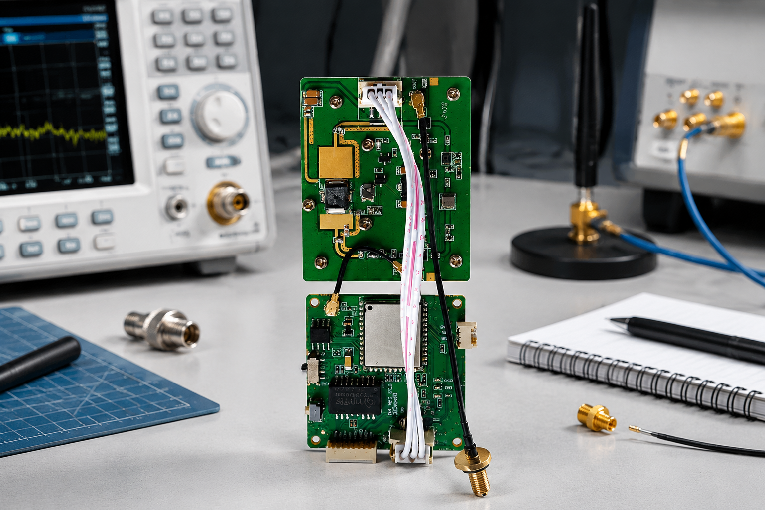
Choosing a WiFi HaLow module for industrial IoT starts with the deployment—not the module catalog. Define the required range, obstructions, data rate, video workload, power source, antenna location, host interface, and environmental conditions before comparing hardware.
The right module should provide enough RF margin for the real installation, connect cleanly to the host processor or camera, fit the enclosure, support the required firmware controls, and remain stable through validation testing. A practical selection process covers eight areas: deployment inputs, interfaces, RF integration, power, firmware, mechanical fit, field testing, and supplier capability.
Define the Deployment and Link Budget Inputs
Before selecting a WiFi HaLow module, document both ends of the wireless link and the conditions between them. A module that works well in an open-area test may not provide the same result through walls, equipment, vegetation, or industrial structures.
Start with these deployment inputs:
- Distance: Record the expected operating distance and the maximum distance that must be supported.
- Geometry: Note whether the link is point-to-point, point-to-multipoint, fixed-to-mobile, or connected through an access point.
- Line of sight: Identify clear line-of-sight paths, partial obstructions, and fully obstructed paths.
- Mounting height: Document the height of the radio and antenna at each end.
- Obstructions: List concrete walls, metal structures, tanks, vehicles, racks, machinery, and other materials in the Fresnel zone.
- Traffic type: Separate telemetry, control messages, sensor data, images, live video, and recorded-file transfers.
- Required throughput: Estimate average throughput, peak throughput, packet frequency, and acceptable latency.
- Reliability target: Define whether occasional retransmissions are acceptable or whether the link supports a safety-related or operationally critical function.
- Regional requirements: Confirm which permitted WiFi HaLow band and channel settings apply to the installation location.
Build a realistic link budget
A link budget estimates whether the received signal should remain usable after accounting for gains and losses. At a basic level, review:
- Transmit power
- Antenna gain
- Cable and connector loss
- Free-space path loss
- Wall, equipment, and foliage loss
- Polarization mismatch
- Fading and multipath margin
- Receiver sensitivity at the required data rate
Do not compare transmit power alone. A higher-power radio may still underperform if the antenna is poorly placed, the enclosure detunes the antenna, or the installation has insufficient fade margin.
The required margin depends on the environment and application. A simple monitoring link may tolerate more variation than a continuous video connection or a control system that must remain connected. Ask the module supplier for the receiver sensitivity and transmit-power behavior for the specific channel, bandwidth, modulation, and regulatory configuration you plan to use. If these values vary by operating mode, evaluate the complete table rather than a single headline number.
Treat video requirements separately from sensor traffic
“Long range” does not automatically mean “suitable for video.” Video performance depends on resolution, frame rate, codec, bitrate, latency, scene complexity, and the amount of interference in the channel.
For a video design, define:
- The source resolution and frame rate.
- The expected encoded bitrate and peak bitrate.
- Whether audio, metadata, or control traffic shares the link.
- The maximum acceptable delay.
- What happens when throughput temporarily drops.
- Whether the application needs one stream or several simultaneous streams.
For sensor networks, the more important factors may be connection density, sleep behavior, packet delivery, network recovery, and battery life. Choose a WiFi HaLow module based on the actual traffic profile rather than assuming that all IoT devices have the same requirements.
Choose the Host and Network Interfaces
The module must match the host device electrically, logically, and operationally. Review the interface on the module side and the interface available from the camera, gateway, industrial computer, or embedded controller.
Common questions include:
- Does the host require USB, Ethernet, SDIO, SPI, UART, or another interface?
- Is the interface intended for high-throughput data, control commands, or both?
- Does the host processor have the required drivers and operating-system support?
- Is the module controlled through a host processor, or does it include enough functionality for the intended architecture?
- Are hardware flow control, reset, wake, and status signals available?
- What voltage levels and power sequencing does the host require?
- How will the module be updated and recovered in the field?
For a camera or video gateway, the data path should be evaluated end to end. A fast wireless interface cannot compensate for a host interface, processor, storage system, or software stack that becomes the bottleneck. For a low-data-rate sensor node, a simpler interface may reduce integration effort and power consumption.
A useful comparison looks like this:
| Selection factor | More important for video gateways | More important for sensor and control nodes |
|---|---|---|
| Host throughput | Sustained data rate and buffering | Predictable command and telemetry transfer |
| Latency | Low and stable end-to-end delay | Fast recovery and timely messages |
| Power behavior | Stable operation under sustained load | Sleep, wake, and low-duty-cycle operation |
| Software | Streaming, network management, diagnostics | Provisioning, reconnect, and fleet control |
| Mechanical design | Heat dissipation and connector access | Compact size and antenna clearance |
Do not assume that a module with a familiar connector is automatically compatible. Confirm pin definitions, signal voltage, grounding, reset behavior, boot mode, supported drivers, and the required host-side software.
For an initial product comparison, you can review WKWIFI’s 38 × 38 mm WiFi HaLow module with PA board and compare its documented integration details with your host design. Product-specific electrical and RF specifications should be verified from the current documentation before design approval.
Plan Antenna and RF Integration
Antenna design can determine whether a WiFi HaLow installation meets its range target. Select the antenna, connector, cable, and enclosure as one RF system instead of treating the antenna as an accessory added at the end.
Choose the antenna location early
The best antenna location is often outside the main electronics compartment or positioned away from large metal surfaces, batteries, motors, displays, and high-speed digital circuitry. In fixed industrial equipment, an external antenna may provide better clearance and easier field replacement. In compact equipment, an internal antenna may simplify assembly but requires careful enclosure and PCB review.
Evaluate:
- Antenna type and supported frequency range
- Required polarization
- Horizontal and vertical clearance
- Ground-plane requirements
- Distance from metal and other antennas
- Coaxial cable length and loss
- Connector type and retention
- Sealing and strain relief
- Service access and replacement process
A metal enclosure can block or detune an internal antenna. Plastic, glass, paint, coatings, and nearby components can also change antenna performance. The final product should be tested with the actual enclosure, cable routing, mounting bracket, battery, and nearby wiring—not only with an evaluation board on a workbench.
Confirm regional and RF configuration details
The usable band, channel plan, transmit power, bandwidth, and antenna gain limits can vary by regulatory domain and product configuration. Ask the supplier which settings are supported for your target market and how the module handles regional configuration.
You should also confirm:
- Whether the stated RF values apply at the module connector or at the antenna
- Whether transmit power changes with channel or bandwidth
- Whether antenna gain must be entered or limited in software
- Whether simultaneous transmit activity affects performance
- How coexistence with other radios is handled
- Whether conducted and radiated measurements are available for the final design
Avoid selecting a module solely from a nominal range claim. Range is installation-dependent and should be tied to a defined antenna, height, orientation, data rate, and obstruction profile.
Review Power and Thermal Constraints
Power planning should cover startup, transmit bursts, receive operation, idle behavior, sleep modes, and recovery. A power supply that works during average operation may still fail when the radio transmits at peak demand.
Check the following before layout:
- Input-voltage range
- Peak and average current
- Startup and reset behavior
- Power sequencing
- Sleep and wake control
- Regulator transient response
- Grounding and return-current paths
- Brownout behavior
- Power consumption during sustained video traffic
For battery-powered devices, estimate energy per operating mode rather than using a single average figure. Include reconnect attempts, firmware updates, signal searches, and periods of poor coverage, because these can consume more energy than normal connected operation.
For powered gateways and cameras, thermal behavior may be more important than battery life. Sustained video transmission can create a continuous thermal load. Check whether the module is near heat-sensitive components, whether the enclosure traps heat, and whether the PCB provides an appropriate thermal path. Validate the design at the highest expected ambient temperature and traffic load.
A module’s power and thermal behavior can change with firmware, RF settings, antenna mismatch, and network conditions. Confirm these variables during prototype testing instead of relying only on a nominal electrical estimate.
Check Firmware and Management Needs
A WiFi HaLow module is not complete from an integration perspective until its firmware and management model fit the product. Ask how the module is configured, updated, monitored, and recovered throughout its service life.
Important firmware questions include:
- Is the module controlled with AT commands, a host driver, an API, or a network management interface?
- Which operating systems and processor platforms are supported?
- How are network credentials provisioned?
- Does the device support secure credential storage?
- How are firmware updates delivered and recovered if an update is interrupted?
- Are logs, signal measurements, connection state, and fault codes available?
- Can the host detect and reset a stalled or disconnected radio?
- Are regional RF settings protected from unintended changes?
- Does the software support the required access-point, station, or bridge behavior?
- How are multiple devices configured consistently during production?
For industrial deployments, diagnostics are especially valuable. Useful telemetry may include received signal level, connection duration, retry behavior, channel information, disconnection reason, and temperature or power-related alarms when supported.
Also define ownership of the software integration. The buyer should know which parts are supplied by the module vendor, which drivers must be developed by the OEM, and which functions depend on a separate host operating system. If a custom interface or firmware behavior is required, document it before ordering prototypes.
Validate Mechanical Integration
A module can meet its electrical requirements and still fail to fit the product. Mechanical validation should include the module outline, component height, connector access, mounting method, antenna clearance, shielding, cable bend radius, and production tolerances.
Create a mechanical checklist covering:
- PCB dimensions and thickness
- Keep-out areas around RF components and antennas
- Mounting holes or retention features
- Connector orientation and mating space
- Shield or heatsink clearance
- Nearby fasteners and metal brackets
- Enclosure wall thickness and material
- Cable routing and minimum bend radius
- Access for programming, diagnostics, and service
- Assembly sequence and rework access
Do not wait until final enclosure design to test antenna placement. Even a small change in the antenna location or cable path can affect the RF result. If the product uses a sealed or ruggedized enclosure, test the complete enclosure early enough to change the mechanical design if needed.
Choose a module form factor that supports the production process as well as the prototype. Consider whether the board can be assembled consistently, inspected, repaired, and replaced. If the design may require custom branding, interfaces, antenna arrangements, or enclosure changes, clarify the supplier’s OEM/ODM engineering scope before committing to a platform.
WKWIFI states that its engineering capabilities include PCB layout, embedded firmware, RF tuning, antenna systems, and OEM/ODM customization of hardware, firmware, antennas, enclosures, branding, and interfaces. Those capabilities may be relevant when the standard module does not match the product architecture, but the exact scope, deliverables, and technical limits should be confirmed for the proposed project. You can learn more on the WKWIFI company page.
Prototype and Field-Test Before Scale
A module should pass both bench validation and representative field testing before production quantities are approved. The goal is not only to demonstrate that a connection can be made, but to identify the conditions under which performance degrades.
Bench-test the complete data path
Start with controlled tests that isolate the major variables:
- Measure throughput in both directions.
- Record latency, jitter, packet loss, and reconnect time.
- Test the required video bitrate or sensor message rate.
- Check performance at different signal levels and data rates.
- Test startup, reset, sleep, wake, and power interruption behavior.
- Monitor current and temperature during sustained traffic.
- Verify the host interface under peak load.
- Test firmware update and recovery procedures.
Use the actual host processor, application software, power supply, antenna, cable, and enclosure whenever possible. A radio-only test can conceal bottlenecks in the camera encoder, operating system, storage, or network application.
Field-test the installation
Field tests should represent the worst credible conditions, not only the easiest path. Test at the maximum distance, around obstructions, at different antenna orientations, and during normal operation of nearby equipment.
Record:
- Location and approximate link distance
- Antenna type, orientation, and mounting height
- Obstructions and enclosure configuration
- Channel and bandwidth settings
- Received signal measurements
- Throughput and packet loss over time
- Reconnect behavior
- Temperature and power conditions
- Video quality or application-level performance
- Results during interference or network congestion
Set acceptance criteria before testing. For example, define the minimum sustained throughput, maximum packet loss, maximum reconnect time, and acceptable application latency. Without predefined criteria, teams may approve a module based on subjective impressions from a short demonstration.
Common mistakes to avoid
Several selection errors recur in long-range wireless projects:
- Choosing by range claim alone: Range is not a complete performance specification.
- Using a generic antenna: Antenna gain, placement, cable loss, and enclosure effects all matter.
- Ignoring peak current: Startup and transmit bursts can cause resets or unstable behavior.
- Testing only in a lab: Industrial obstructions and multipath can change results substantially.
- Underestimating host bottlenecks: The processor, driver, or camera pipeline may limit throughput.
- Leaving firmware undefined: Provisioning, updates, logs, and recovery are part of the product.
- Scaling before design freeze: A small PCB or enclosure change can require another RF validation cycle.
- Treating video and telemetry as identical: They have different throughput, latency, and recovery requirements.
For a different mechanical and power approach, review the WiFi HaLow Type-C powered module as another product option to compare against the host architecture and enclosure constraints. Confirm its current specifications and intended integration method before using it in a design.
Questions to Ask an OEM or ODM Partner
A capable partner should be able to answer specific engineering and production questions without reducing the evaluation to a single range figure. Ask for information that maps directly to your deployment and validation plan.
RF and antenna
- What transmit-power and receiver-sensitivity values apply to the intended configuration?
- Which regional settings and channels are supported?
- What antenna options and connector arrangements are available?
- Are antenna tuning and RF layout support included?
- What information is needed to evaluate the final enclosure?
- How are cable and connector losses accounted for?
Electrical and mechanical
- What are the input-voltage, peak-current, and average-current requirements?
- What power sequencing and reset behavior does the module require?
- What are the board dimensions, component heights, and keep-out zones?
- Which host interfaces and voltage levels are supported?
- What thermal conditions should be used for validation?
- Can the design be adapted for a custom PCB, enclosure, connector, or antenna?
Firmware and production
- Which host operating systems, drivers, and APIs are supported?
- How are provisioning, diagnostics, and firmware updates handled?
- What recovery method is available after a failed update or lost connection?
- Which functions are standard and which require customization?
- What test documentation is supplied for production validation?
- How are hardware and firmware revisions controlled during the project?
Project definition
- Which specifications are guaranteed, and which are reference values?
- What tests should the buyer perform before design approval?
- What information must be provided for an OEM/ODM quotation or engineering review?
- How will changes to the module, firmware, antenna, or enclosure be documented?
- Which requirements must be confirmed for the target market and final product?
The best partner is not necessarily the supplier with the highest advertised output power. It is the one that can connect the module’s RF behavior, software, mechanical design, and validation process to your actual product requirements.
Make the Selection With a Requirements Matrix
Before choosing a WiFi HaLow module, create a short requirements matrix and mark each item as required, preferred, or to be verified. Include:
- Deployment distance and geometry
- Required data rate and latency
- Point-to-point or multipoint topology
- Host interface and operating system
- Regional RF configuration
- Antenna and enclosure arrangement
- Input voltage and peak current
- Thermal operating conditions
- Firmware management and update process
- Module dimensions and mounting
- Field-test acceptance criteria
- OEM/ODM customization needs
Then compare candidate modules using the same assumptions. This prevents a product with a convenient form factor from being selected before its antenna, firmware, or power requirements are understood.
WKWIFI was established in 2013 and focuses on WiFi HaLow wireless video and data transmission products. Its facilities include standardized workshops for SMT, PCBA, testing, and final assembly, while its engineering scope includes PCB layout, embedded firmware, RF tuning, antenna systems, and OEM/ODM customization. For an evaluation, use those capabilities as discussion points—but verify the specific module specifications, test evidence, customization scope, and project requirements that apply to your design.
A practical next step is to document your target range, traffic type, host interface, antenna location, power source, enclosure, and acceptance criteria. You can then review the relevant WiFi HaLow module options and discuss only the verified technical requirements that remain unresolved.