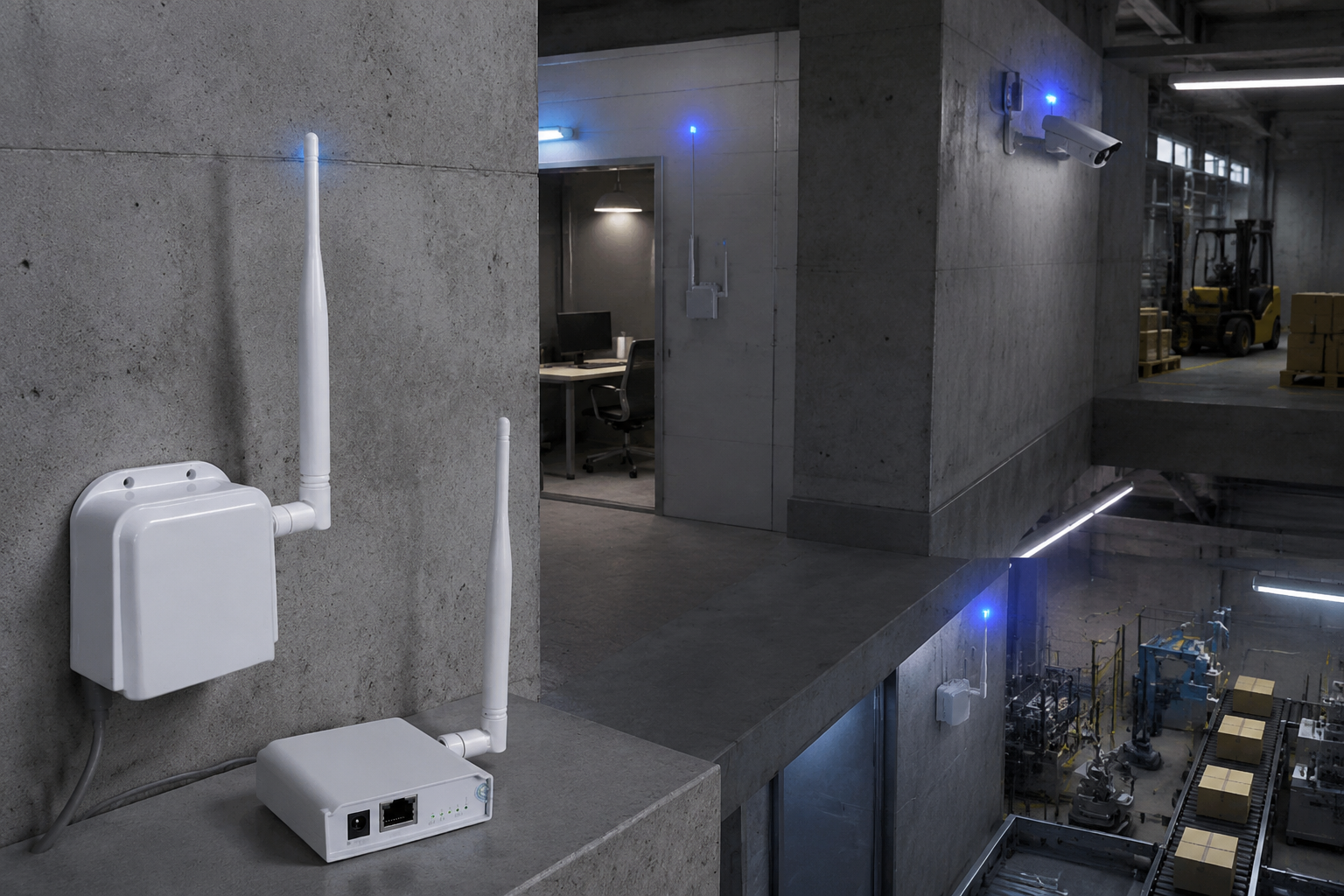
WiFi HaLow can generally travel farther and penetrate typical building materials more effectively than 2.4 GHz or 5 GHz Wi-Fi because it operates in sub-GHz spectrum. However, the actual result depends on frequency, channel width, transmit power, antenna design, receiver sensitivity, data rate, obstructions, interference, and local regulations.
A useful way to evaluate WiFi HaLow range and wall penetration is to treat published distance as a starting point—not a guarantee. For a dependable deployment, measure the signal and application performance at the intended mounting locations, through the actual walls, doors, floors, and outdoor obstacles.
Why Sub-GHz Signals Behave Differently
WiFi HaLow is based on IEEE 802.11ah and uses sub-GHz frequencies. Compared with conventional Wi-Fi bands, the longer wavelength can reduce free-space path loss and improve diffraction around some obstacles. In practical terms, a sub-GHz signal may maintain a usable connection farther from an access point or pass through more building material than a similar 2.4 GHz or 5 GHz link.
That advantage does not mean sub-GHz wireless signals pass through everything without loss. Every wall, ceiling, vehicle, piece of equipment, and section of vegetation can reduce the available link margin. The number and type of obstacles matter as much as the advertised radio range.
Range is a link-budget result
Wireless range is determined by the relationship between transmitted energy and the receiver’s ability to decode the signal. Important variables include:
- Transmit power and antenna gain
- Antenna cable and connector losses
- Receiver sensitivity at the selected data rate
- Channel bandwidth
- Modulation and coding
- Frequency and channel conditions
- Height and location of both antennas
- Building materials and other obstructions
- Interference and background noise
- Required throughput and latency
A link may remain technically connected while delivering too little throughput for video, control traffic, or time-sensitive data. For that reason, “range” should always be defined alongside the application requirement.
A low-bandwidth sensor may work at a distance where a high-resolution video stream does not. Similarly, a connection that works outdoors with clear line of sight may fail when one endpoint is moved behind reinforced concrete or metal equipment.
Materials That Affect Wall Penetration
Wall penetration varies substantially by construction. A lightweight interior partition and a reinforced concrete wall should not be treated as equivalent obstacles. Moisture, density, thickness, metal reinforcement, insulation, and the angle at which the signal crosses the wall can all change the result.
The following comparison is a practical starting point, not a substitute for testing at the site.
| Building material or obstacle | Typical impact on a sub-GHz link | What to watch for |
|---|---|---|
| Drywall and wood framing | Often lower loss than dense construction | Multiple partitions still add up |
| Glass | Variable | Tinted, coated, or treated glass may include conductive layers |
| Brick or block | Moderate to high loss depending on thickness and moisture | Older or unusually thick walls may behave differently |
| Concrete | High and highly variable loss | Thickness, density, and reinforcement are important |
| Reinforced concrete | Often among the most difficult indoor barriers | Steel can absorb, reflect, or scatter energy |
| Metal doors and panels | Potentially severe attenuation or blockage | Openings and reflections can change results |
| Insulated walls | Variable | Foil-backed insulation can be especially challenging |
| Water, tanks, and wet materials | Can absorb significant RF energy | Industrial environments may change over time |
| Vegetation | Variable and often seasonal | Wet leaves and dense foliage usually create more loss |
Why metal is especially difficult
Metal can reflect radio energy, block direct paths, and create multipath. A signal may appear strong in one position and weak only a few feet away because reflected paths reinforce or cancel each other. Metal shelving, machinery, elevator shafts, shipping containers, and electrical cabinets can therefore produce results that are difficult to predict from a floor plan alone.
Crossing a wall at an angle
A radio path that crosses a wall diagonally travels through more material than one that crosses it perpendicularly. This can matter in large facilities where the access point and client are located on different sides of a building or where the signal must pass through several angled partitions.
When possible, plan the link so that the signal crosses fewer walls and travels through them as close to perpendicular as the site allows.
Antenna Placement and Polarization
Antenna placement can improve a difficult link without changing the radio hardware. Mounting an antenna behind a cabinet, inside a metal enclosure, near a large motor, or directly against a concrete surface can reduce performance even when the selected device has adequate theoretical range.
For most deployments:
- Place the antenna in a clear location rather than inside or immediately beside metal.
- Keep it away from large power equipment and dense wiring when practical.
- Avoid burying the antenna behind a rack, panel, or thick wall.
- Use the intended antenna orientation at both ends of the link.
- Minimize unnecessary coaxial cable length and connector transitions.
- Leave room for adjustment during commissioning.
- Consider antenna height, especially where people, vehicles, or equipment may obstruct the path.
Polarization must match
Antennas radiate and receive with a particular polarization, commonly vertical or horizontal. The transmitting and receiving antennas should use compatible orientations. A significant mismatch can reduce the received signal even when the distance and frequency are otherwise suitable.
For fixed links, mark the intended antenna orientation during installation. For mobile or changing endpoints, account for the fact that device rotation can alter polarization alignment and multipath behavior.
Integrated versus external antennas
An integrated antenna may simplify installation, while an external antenna can provide more placement flexibility. The correct choice depends on enclosure design, mounting constraints, antenna clearance, and the required link budget.
Do not judge a radio by antenna gain alone. A higher-gain antenna may have a narrower radiation pattern, making alignment more important. It may also be unsuitable for a particular enclosure or regional power limit. Confirm the complete radio-and-antenna configuration rather than evaluating the antenna as an isolated component.
Transmit Power Sensitivity and Data Rate
Increasing transmit power can improve link margin, but it is not a universal solution to wall penetration. The receiver still needs a sufficiently clean signal, and the return path must also work. A high-power access point cannot compensate for a poorly placed or low-sensitivity client.
Transmit power is only one part of the link budget. Also consider:
- Receiver sensitivity at the required modulation
- Antenna gain and radiation pattern
- Cable and connector loss
- Channel bandwidth
- Regulatory power limits
- The transmit capability of both endpoints
- Thermal and power constraints of the installed hardware
Lower data rates often extend usable range
Wireless systems generally achieve their longest range at more robust modulation and coding settings. Higher data rates require better signal quality and more link margin. If the link becomes weak, the system may reduce its data rate to maintain connectivity.
This creates an important distinction:
- Connection range: the distance at which devices can still exchange traffic.
- Usable application range: the distance at which the link meets throughput, latency, packet-loss, and reliability requirements.
- Video range: the distance at which the link can sustain the selected video resolution, frame rate, codec, and network overhead.
A link that supports telemetry may not support a stable video stream. When evaluating a WiFi HaLow bridge or video product, test with the intended payload rather than relying only on association status or a basic ping.
Channel width involves a tradeoff
Wider channels can support more throughput under suitable conditions, but they may require better signal quality and may interact differently with local spectrum rules and interference. Narrower channels can be useful when range, coexistence, or channel availability is more important than peak throughput.
The appropriate setting depends on the application. A sensor network, control system, and wireless video link may have different requirements even at the same physical location.
Interference Noise and Regional Rules
Sub-GHz spectrum is not automatically interference-free. Other systems may share nearby frequencies, and industrial environments can contain electrical noise, switching equipment, motors, and poorly shielded electronics. The lower frequency may improve propagation while still leaving the link vulnerable to congestion or local noise.
Before selecting a channel or product, verify:
- Which frequencies and channel widths the equipment supports
- Whether those settings are permitted in the intended US deployment
- Maximum allowed power and antenna combinations
- Indoor, outdoor, mobile, and fixed-use restrictions
- Whether the device firmware supports the required regional configuration
- Whether the installation creates coexistence concerns with other systems
In the United States, applicable FCC requirements and device-specific operating rules must be checked for the exact hardware, antenna, frequency, and installation. A product’s nominal range does not override regional spectrum restrictions.
Noise can matter more than distance
A short link in a noisy environment may perform worse than a longer link in a quiet one. Record signal strength and noise conditions during a site survey, and repeat measurements at different times if the environment changes with shifts, machinery, vehicle traffic, or production schedules.
If a link is marginal, first investigate placement, antenna orientation, channel selection, and obstructions. Increasing power without understanding the noise source may raise interference without producing a reliable application connection.
How to Run a Useful Site Survey
A site survey should reproduce the intended installation as closely as possible. Testing two radios on a workbench or in an empty parking lot can confirm basic operation, but it does not predict wall penetration through a finished building.
Use this repeatable process.
1. Define the application requirement
Write down what the link must support:
- Required throughput in each direction
- Video resolution, frame rate, and compression settings if applicable
- Maximum acceptable latency
- Tolerable packet loss or retransmissions
- Availability or uptime target
- Whether the endpoint is fixed, mobile, or intermittently obstructed
- Power and enclosure constraints
This prevents an ambiguous “long range” requirement from driving the design.
2. Map the actual path
Create a simple floor plan or site sketch showing:
- Proposed radio locations
- Wall and floor materials
- Metal structures and large equipment
- Doors, windows, shafts, and corridors
- Antenna heights and orientation
- Outdoor obstacles and expected vehicle movement
Count the barriers between endpoints. Note whether the path crosses reinforced concrete, metal-clad areas, or rooms containing tanks or machinery.
3. Install antennas in representative positions
Use the planned mounting height and approximate final antenna orientation. If the final enclosure, cable, or bracket is known, include it in the test. Keep temporary test equipment from being placed in a more favorable position than the final installation.
4. Measure multiple locations
Test the intended endpoint and nearby alternatives. A change of a few feet can improve a multipath-affected link, especially around metal structures. Take measurements on both sides of difficult walls and at the edge of the expected coverage area.
5. Test the real traffic
Measure more than received signal strength. Run traffic that resembles the final application and record:
- Sustained throughput in both directions
- Latency and jitter
- Packet loss
- Retransmissions or link-rate changes
- Video freezes, dropped frames, or visible artifacts
- Recovery after temporary obstruction or endpoint movement
For video, test the actual camera profile or a realistic traffic load. A speed test with no video overhead may overstate practical performance.
6. Test under realistic conditions
Repeat the survey with doors closed, equipment operating, vehicles present, and normal building occupancy when those conditions affect the path. If the site changes by season or production schedule, include those conditions in the risk assessment.
7. Record a design margin
Do not design directly at the point where the link barely works. Leave margin for changing noise, small antenna shifts, weather, construction changes, and future traffic. The exact margin needed depends on the application and environmental variability, so it should be established through the project’s reliability requirements rather than copied from a generic rule.
How to Interpret Range Specifications
A range specification is meaningful only when its test conditions are clear. Ask what the stated distance represents and whether it applies to line-of-sight operation, indoor wall penetration, a particular antenna, a particular data rate, or a specific throughput target.
When comparing products, request or verify:
| Specification to check | Why it matters |
|---|---|
| Frequency and supported channels | Determines propagation and regional compatibility |
| Channel bandwidth | Affects throughput, sensitivity, and spectrum use |
| Maximum transmit power | Must be evaluated with antenna gain and local rules |
| Receiver sensitivity | Indicates decoding capability at defined data rates |
| Antenna type and gain | Changes coverage pattern and link budget |
| Interface speed | Limits the traffic the device can deliver to the network |
| Measured throughput | More useful than connection status alone |
| Test environment | Separates line-of-sight claims from indoor performance |
| Wall count and material | Makes penetration claims easier to interpret |
| Application payload | Shows whether the result supports video or data |
A “3 km” or “300 m through a wall” label should not be treated as a universal indoor guarantee. Such figures may describe a specific test configuration, open-air path, endpoint height, antenna arrangement, or minimum connectivity threshold. Confirm the conditions and compare them with the planned installation.
For a product intended to connect buildings or distant fixed endpoints, review a purpose-built WiFi HaLow bridge for longer links. For a shorter wall-penetrating connection, a 300 m wall-penetrating wireless bridge may be a relevant starting point, subject to site validation and application requirements.
A Deployment Validation Checklist
Use this checklist before approving a WiFi HaLow installation:
- The required throughput, latency, packet-loss tolerance, and video profile are documented.
- The intended frequency, channel width, transmit power, and antenna configuration are permitted for the US deployment.
- Both endpoints support compatible WiFi HaLow modes and network interfaces.
- Antenna type, gain, connector, cable length, and polarization are documented.
- The path has been reviewed for concrete, reinforcement, metal, glass coatings, water, and machinery.
- Antennas are not enclosed by or mounted directly against large metal surfaces.
- The survey used representative mounting locations and final or equivalent enclosures.
- Measurements were taken at the farthest endpoint and at likely weak spots.
- Testing included bidirectional application traffic, not only a ping or association test.
- Video was tested at the intended resolution, frame rate, and compression settings.
- Testing covered normal operating conditions, including equipment and doors that affect the path.
- Results were recorded for signal, noise, throughput, latency, packet loss, and link-rate changes.
- The design includes practical margin rather than operating at the minimum observed threshold.
- A fallback mounting position or alternate path has been identified.
- Future construction, equipment movement, and seasonal obstructions have been considered.
When comparing hardware, also verify the interfaces, firmware features, antenna options, enclosure requirements, and management functions needed by the deployment. These details can determine whether a radio is merely compatible on paper or suitable for integration into a production network.
WKWIFI focuses on WiFi HaLow wireless video and data transmission products and supports engineering work involving PCB layout, embedded firmware, RF tuning, antenna systems, and OEM/ODM customization. If a project requires a customized hardware, firmware, antenna, enclosure, branding, or interface configuration, review the available WKWIFI engineering and company information and confirm the exact range, interface, and deployment requirements with the engineering team.
The most reliable way to judge WiFi HaLow range and wall penetration is to combine the radio specification with a site-specific link budget and a measured application test. Start with the required traffic, map the physical path, test the actual obstacles, and select equipment only after the results match the deployment’s reliability target.